As the core of CNC machine tools, the servo system ensures the normal operation of the machine tool. Once a fault occurs, the impact range and consequences are extremely large. The article introduces the composition and classification of servo systems in CNC machine tools, as well as the types of servo system faults. It elaborates on the basic maintenance process and common maintenance methods for common faults in CNC machine tool servo systems, and finally summarizes the common fault handling measures for CNC machine tool servo systems.
The core of the work of CNC machine tools is the servo system. The servo system of CNC machine tools is the hub between the mechanical transmission components of the machine tool and the CNC system. The servo system is in frequent starting, braking and other action processes during the dynamic operation of the machine tool, and has the highest failure rate. Therefore, the stability and reliability of the servo system directly affect the quality and efficiency of part processing. How to solve the technical difficulties in the maintenance of CNC machine tools is a major issue facing the field of CNC machine tool maintenance.
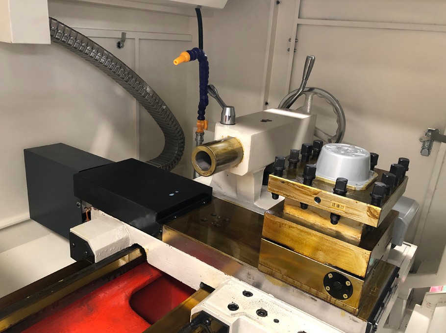
1. CNC machine tool servo system
The servo system of a CNC machine tool consists of a drive unit, actuators, mechanical transmission components, and detection feedback links. The types of servo systems for CNC machine tools can be divided into open-loop CNC systems and closed-loop CNC systems based on whether the feed servo subsystem of the CNC system has a position measurement device; According to the classification of using DC servo motors and AC servo motors, they can be divided into DC servo systems and AC servo systems; According to the classification of feed drive and spindle drive, it can be divided into feed servo and spindle servo systems; According to feedback comparison control methods, there are pulse digital comparison servo systems, phase comparison servo systems, amplitude comparison servo systems, and fully digital servo systems. The servo system converts and amplifies the displacement and other signals received, and then drives the corresponding machine spindle and tool holder to work through the mechanical transmission system, thereby completing the corresponding precision actions.
2. Types of faults in servo systems of CNC machine tools
The faults of servo systems are generally divided into feed servo system faults and spindle servo system faults. 2.1 Feed servo system fault (1) Overtravel: When the motion stroke exceeds the soft limit or switch limit setting range, an overtravel alarm will occur. (2) Motor not rotating: Loss of enable control signal or absence of speed control signal can cause the servo motor to not rotate. (3) Bounce: Unstable signals, poor contact of wiring terminals, unstable or interfered speed control signals can all cause bouncing phenomena. (4) Overload: Frequent forward and reverse rotation, poor lubrication, and excessive load can all cause overload alarms. (5) Machine tool vibration: The high-speed movement of the machine tool causes vibration, and the vibration problem originates from the speed issue. The speed loop can be queried. (6) Crawling: Excessive external load, low gain of servo system, poor lubrication of transmission chain, loose coupling connection, and defects in the coupling itself can all cause crawling phenomenon. 2.2 Spindle servo system failure (1) Overload: frequent forward and reverse rotation, input power phase loss, excessive cutting amount, etc. (2) Interference: Poor shielding and grounding, external electromagnetic interference, interference with feedback signals or spindle speed command signals. (3) Motion mismatch: inaccurate encoder pulse feedback signal, etc. (4) Abnormal speed: The spindle speed exceeds the specified range value. (5) Abnormal noise: The spindle vibrates and produces abnormal sounds during operation. (6) Quasi stop shaking: When changing or retracting the tool, the spindle positioning shakes. (7) The spindle does not rotate: The spindle motor does not rotate during operation.
3. Basic maintenance process for common faults in servo systems of CNC machine tools
When repairing the servo system of a CNC machine tool, the basic idea is the same as that of machine tool maintenance, which basically adopts the "look, smell, ask, cut, apply" maintenance process steps. "Look, smell, ask" is to understand the fault phenomenon, "cut" is to analyze the cause of the fault, find the faulty component, and "apply" is to solve the actual fault problem. The specific implementation process is as follows: (1) When a fault occurs, people first habitually use the naked eye to conduct a preliminary inspection, determine the operation status and alarm information of the machine tool they see. (2) Wen: When electrical components are overloaded, they may burn out. Sensing the problem through smell is also one of the ways to diagnose faults. (3) Q: When maintenance personnel arrive at the scene and cannot identify the fault based on what they see or smell, it is necessary for maintenance technicians to ask the on-site operators about basic machine tool issues, including abnormal machine tool sounds or abnormal operating conditions heard. (4) Cut: After conducting preliminary diagnosis in the previous steps, in order to further understand the fault problem, maintenance technicians can operate relevant testing instruments and meters, deeply diagnose the cause of the fault, and ultimately determine the location of the fault. (5) Shi: After the fault problem is identified, prepare a maintenance plan, prepare data materials, prepare corresponding maintenance tools, adopt corresponding matching maintenance methods to handle the fault, and finally conduct functional testing to solve the fault problem.
4. Common maintenance methods for common faults in servo systems
(1) Component replacement method. The component replacement method, also known as the module exchange method, can be used for fault prediction due to the modular design of servo system components and the interchangeability between modules. (2) Short circuit method for power lines. When a component in the system circuit burns out, it may cause a short circuit. A multimeter can be used to detect the input and output terminals of the component, check for a short circuit, and thus identify the cause of the fault. (3) Enabling condition method. The servo motor needs to meet the enabling conditions in order to work, and the cause of the fault can be determined and eliminated by changing the enabling conditions for inspection. (4) Reference voltage method. When a certain axis malfunctions, in order to determine whether the drive module or motor module is faulty, the speed ring can be disconnected and the position ring can be checked. (5) Parameter testing method. When a CNC machine tool experiences a crawling fault, it may be due to the servo system gain being too low, and the problem needs to be verified by changing the parameters. (6) Measurement method. When no physical structural problems are found in the components of the system after inspection, it is possible to choose to check their voltage and current values to determine whether the fault is caused by insufficient voltage and current.
5. Common troubleshooting of servo systems in CNC machine tools
5.1 Fault handling of feed servo system
(1) TMP indicator light red: Check if the driver is overheated and if the motor is overloaded. (2) DIS indicator light yellow: Check if the driver enable signal (+ENA/- ENA) is connected correctly. (3) The LED indicator light is green and the motor is not moving: check if the+INHIBIT and - INHIBIT ports are connected incorrectly, and if the command signal ground is connected to the driver signal ground. (4) Motor rotation, LED flashing: Check if the motor phase setting switch is correct and if the sensor voltage value is within the range. (5) Driver LED light not on: Check if the power supply voltage is less than the minimum voltage value. (6) The LED light remains red: check whether the input voltage of the driver is overvoltage or undervoltage, whether the motor is short circuited between phases, and whether the motor is overloaded and overheating. (7) Unstable positioning accuracy of the transmission system: Check if the screw nut is installed correctly. (8) The positioning error of the transmission system is relatively large: check whether the pitch error of the screw is too large, and whether the connection between the motor and the screw is loose. (9) Motor stall: Check if the speed feedback polarity is reversed and if the encoder power supply has lost power. (10) Excessive positioning error of reference point: Check whether the proximity switch is installed correctly, whether the gap between the proximity switch and the detection object is sufficient, and whether the proximity switch is faulty. (11) Thread machining cannot be repeated: Check if the mechanical connection between the spindle and spindle encoder is normal. (12) Deviation counter overflow error occurs when the motor rotates at high speed: check whether the motor and cables are damaged, whether the wiring of the power cable and encoder cable is correct, whether the deviation counter overflow of the motor is incorrect, whether the gain setting is correct, and whether the motor load is within the allowable range. (13) Incorrect return reference point action: Check if the logic proximity switch needs to be replaced and if the contact switch has been reset. (14) The motor runs faster in one direction than in another: check if the brushless motor phase is incorrect, if the test/deviation switch is in the test position, and if the deviation potentiometer position is correct. (15) The servo motor does not operate when there is pulse output: check whether the control mode is in position control mode, whether the encoder cable is configured incorrectly, whether the brake of the servo motor with brake has been opened, whether the Run command is normal, monitor the controller panel to confirm whether the pulse command is input, monitor whether the controller pulse is output normally, whether the input pulse is consistent with the command pulse setting, and whether the deviation counter reset signal is input.
5.2 Fault Handling of Spindle Servo System
(1) The spindle does not move and there are no alarms: check whether the mechanical load is too large, whether the connection between the spindle and the motor is too loose, whether the tool or workpiece is clamped properly, whether the power line is connected normally, whether the enable signal is normal, and whether the driver or motor is damaged. (2) Invalid spindle speed command: Check if the power connection is normal and if the CNC circuit board is damaged; Check whether the feedback signal is normal, whether the feedback line connection is normal, and whether the spindle driver parameters are set improperly. (3) Excessive speed deviation: Check whether the feedback connection is normal, whether the feedback device is damaged, whether the power line connection is normal, whether the power voltage is normal, whether the cutting load of the machine tool is too large, whether the brake circuit is normal, and whether the motor and driver are damaged. (4) Excessive spindle vibration or noise: Check if the power system is out of phase or has abnormal voltage, if the load is too heavy or poorly lubricated, if the drive belt is too tight, if the bearings and gears are damaged, if the machine clearance is normal, and if the pre tightening screws are loose. (5) The spindle does not work properly during acceleration/deceleration: check if the relevant parameter settings are normal, if the feedback device is functioning properly, and if the inertia between the motor and the load matches. (6) Random fluctuations in spindle speed: Check if the shielding and grounding are normal, and if the spindle speed command signal and feedback signal are disturbed. (7) The spindle cannot be variable speed: check if the CNC parameter settings are improper, if the machining program programming is incorrect, and if there are any faults in the D-A conversion circuit and speed analog input circuit. (8) Irregular threads: Check if the encoder is functioning properly, if the coupling is loose or broken, if the spindle speed is unstable, and if there are any issues with the machining program. (9) Unstable spindle positioning point: Check if the limit switch is damaged, if the feedback line connection is poor, and if the encoder is functioning properly. (10) Insufficient spindle output: Check the clearance of the drive belt and whether the spindle motor is faulty. (11) The spindle cannot work properly: Check if the elastic knife is in place, if the spindle gear is in position, if the cutting is overloaded, if the driver is overheated, if the spindle motor module is faulty, and if the mechanical parts of the host are damaged.
6. Conclusion
Numerical control machine tools are the guarantee for the development of the national manufacturing industry. Solving the problem of machine tool maintenance can greatly promote the economic development of the country. This article briefly introduces the types of faults and maintenance methods of the servo system of numerical control machine tools, and focuses on the common fault maintenance measures of the servo system of numerical control machine tools, providing some reference for the fault maintenance of numerical control machine tools.
Prev Page:Do you know the characteristics of CNC lathes?
Next Page:没有了…
If you have any suggestions for our products or services, please leave me a message in a timely manner!
Contact us is the way to solve the problem